
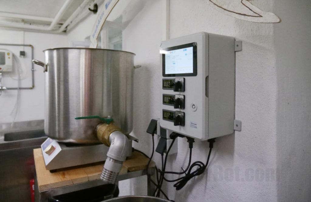
The Raspberry Pi is great for building brewing and fermentation controls. It offers an insane amount of flexibility – feel free to deviate from this guide depending on your needs. We will guide you how to build a Raspberry Pi based brewing control using the free BierBot Bricks software step-by-step. It offers recipe management, controlling your agitators/ pumps, automatically recording beautiful logs and a nice web UI for your smartphone (iOS, Android) that’s available from everywhere. If you need just one relay and temperature probe, checkout the super simple Sonoff TH16 based build.
YouTube Video
Checkout the related YouTube video:
Preliminary considerations
As of today, there are three main platforms to build a brewing control:
| System | Advantages | Disadvantages |
|---|---|---|
| Raspberry Pi | ➕ Plenty of GPIOs. ➕ Insane amount of compute power on the device. ➕ Huge flexibility (Logging). ➕ WiFi enabled, thus WebUI capable. ➕ Smartphone (Android / iOS enabled). ➕ Bluetooth enables new possibilities, e.g. TILT integration. | ➖ Pricy (Raspberry Pi + a fair amount of other stuff + tools required). ➖ Time consuming to build. |
| ESP8266 | ➕ The Sonoff TH 16 is suitable “out of the box” – you just have to flash a different firmware. ➕ Cheap, as the Sonoff TH16 and a temperature probe only cost 20€/USD. ➕ WiFi enabled, thus WebUI capable. ➕ Smartphone (Android / iOS enabled). | ➖ Limited GPIO – only one relay available on the TH16. ➖ No display available on the device. |
| Arduino | ➕ Easy tooling, great to learn embedded. ➕ Free, Arduino based homebrewing software. | ➖ Time consuming to build. ➖ No WebUI / WiFi. ➖ No Logging |
The bottom-line: The Arduino is nowadays only a viable option if you want to learn embedded programming. Other than that, there is no real reason to use Arduino as it shares most of the disadvanges of other build while not offering any advantages. If you want a modern, smartphone interface, ESP8266 and Raspberry Pi remain. The ESP8266 is the better choice, if you’re just getting started and need only one Relais. We show you how to build a brewing / fermentation control based on ESP8266 here. A Raspberry Pi based built offers anything the ESP8266 build offers with more flexibility, features, support for multiple relays, a display, and much more. This is why, the longer build time pays off and why a Raspberry Pi based build is our recommendation for the ambitious homebrewer. Enough said… Let’s go!
A word of warning
⚠️ DANGER OF ELECTROCUTION ⚠️ This manual is only for Experts
If your device connects to mains electricity (AC power) there is danger of electrocution if not installed properly. If you don’t know how to install it, please call an electrician (Beware: certain countries prohibit installation without a licensed electrician present). Remember: SAFETY FIRST. It is not worth the risk to yourself, your family and your home if you don’t know exactly what you are doing. Never tinker or try to flash a device using the serial programming interface while it is connected to MAINS ELECTRICITY (AC power).
We don’t take any responsibility nor liability for using this software nor for the installation or any tips, advice, videos, etc. given by any member of this site or any related site.
Outline
The brewing control we will build in following has these technical characteristics:
- 2x AC out, 10Amps each, 230V, 3.5kW
- 3x 24V DC out, 120W + 60W + 60W
- Possibility to set Voltage using a motor governor on the device for DC.
- A 7″, 800 x 480 pixel touchscreen display.
- Two temperature probes (Mashtun / Spargetun or for HERMS setups)
The build includes the following steps. You’ll find the build time estimations in brackets.
- Sketching where to cut / drill the housing (3 hours)
- Cutting the housing (3 hours)
- Installing the sockets on the housing (4 hours)
- Connecting the wires and preliminary tests (3 hours)
- Building a baseplate and mounting everything on it (2 hours)
- Installing and configuring the software (0.5 hours)
What you will need
Materials
Please feel free to enhance or shorten the list as you might have different requirements. This is the aforementioned “flexibility” a RaspberryPi based solution offers😉 To save you money, I’ve split the materials list into essentials and nice-to-haves.
Essentials
- The Free, BierBot Brewing-Software from Github.
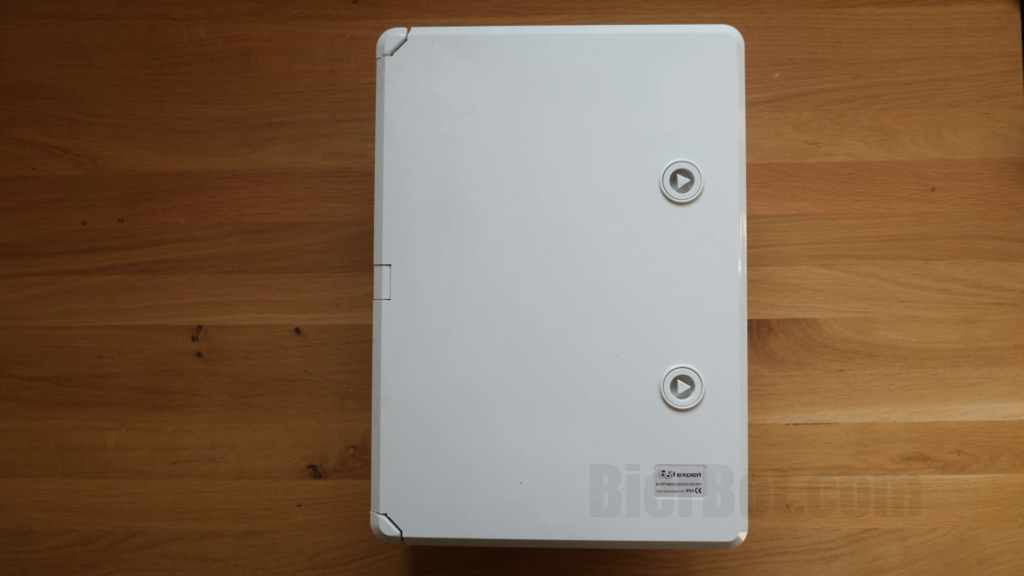
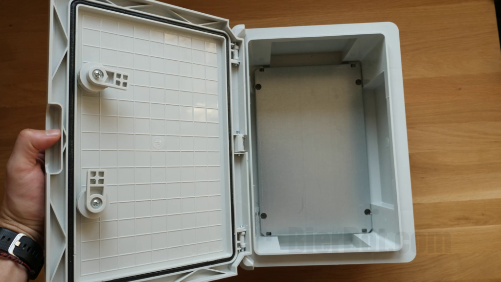
- A housing, I’ve used the expert BXPPABSG250350150-F01. It’s 350x250x150mm (13.8×9.8×5.9 in) on the outside, and has 305x195x130mm (12×7.7x51in) for build volume on the inside. It’s also IP65 rater – a big plus in humid breweries. (34€)
- 40cm / 16in female to female jumper cable. This connects the RaspberryPis GPIOS to the Relais for for switching the AC. Don’t fall for the shorter ones (e.g. do NOT use the 20cm / 8in) ones. These will be most likely too short. Google for “jumper cable female to female”.
- A Raspberry Pi. If you want a display built in into your brewery control, I’d recommend using a Raspberry Pi 3 (or later, i.e. Raspberry Pi 4, etc.). If you just need a bunch of GPIO, the Raspberry Pi 2 is fine. However, please bear in mind, that starting with the Raspberry Pi 3, WiFi and Bluetooth is already on board. Thus, you save the money for an USB-WiFi or USB-bluetooth card.
- A power brick for your Raspberry Pi (Raspberry Pi 3, Raspberry Pi 4).
- A SD-Card– 16GB is absolutely large enough. If you have a spare one lying around, just use that one – you won’t be able to tell any difference.
- A Relay-Board to control the heating during mashing or cooling during fermentation.
- A LED power supply as our AC to DC converter. I’ve used four Meanwell LPV-60-24 (since I had them laying around). They provide 60W @ 24V. The main DC output is powered by 2 (120W), the remainig two by one each, respectively. Advantage: If one fails, the other(s) will still work.
- A temperature sensor. I prefer the Sonoff TH16 compatible DS18B20. It has a nice 2.5mm AUX-Jack.
- A socket to plug in the temperature sensor, I had two AL560 extension cables lying around. Any other 2.5mm TSSR connector works, though.
- AC cord, 3×1.5mm² / AWG16 (3m), just buy an extension cable and cut it.
- DC cord, 2×1.5mm² / AWG16 (3m), I’ve actually used speaker cable (nice isolation, red/black wires inside).
- 2x AC-Out-Sockets.
- 3x AC-In Sockets. If you can, get crimped connectors to slot onto. If have soldered it. That’s, however, not advisable as solder get soft when being warmed up.
- 3x plugs that fit into the aforementioned sockets. I’ve used C19 plugs to support 16A.
Nice-to-haves
- Display for the Pi – a very nice but expensive addition.
- XLR socket to connect your DC equipment such as pumps, agitators, etc.
- Switches / knobs to manually turn on / off your DC outlets. I’ve started with two-way on/off switches, but than switched (😉) to on/off/controlled by the Raspberry Pi (a.k.a. three way) switches.
- DC regulator to control the pump speed: https://amzn.to/35CaPDV
Tools
Better tools, make your life easier, reduce your build-time and will improve the quality of result. However, many tools can be replaced by other tools (e.g. multi-tool by a jigsaw). Also: I’d like to encourage you to improvise whenever save.
Required
- Drilling machine to drill holes into the housing.
- Something to cut the housing, e.g. Jigsaw (optimal would be a Multitool, see “Nice-to-have”)
- Something to strip cables, I personally love the Knippex Multistrip 10. However, a Leatherman will do as well.
- Soldering iron
- Screwdriver, I’d recommend going for a Bit Screwdriver (so you always have the fitting Bit).
Nice-to-have
- Multi-tool (e.g. Makita DTM51Z) to cut out the housing.
Sketching where you want to cut
Cut before you think – wait, it’s the other way around. In this case, it’s actually plan and sketch before you cut. I always try to fit as much as possibly into the minimum space. Even if this does not sound like you, I strongly recommend carefully sketching all planed holes as well as all outlines of everything that is going to be located on the housing.
Take, e.g., the RaspberryPi display. The required cutout for the display is a good 20mm / 0.8in smaller than the actual display. Not thinking about that will most likely cause collisions with other components, unless your layout is really generous with space.
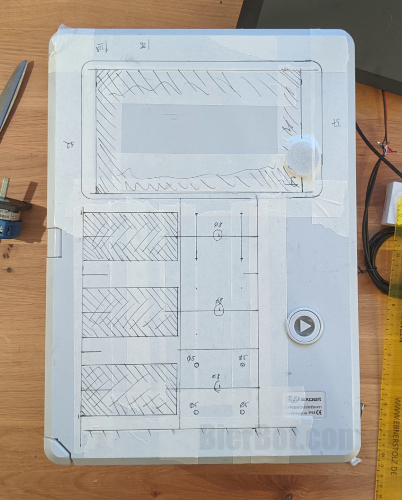
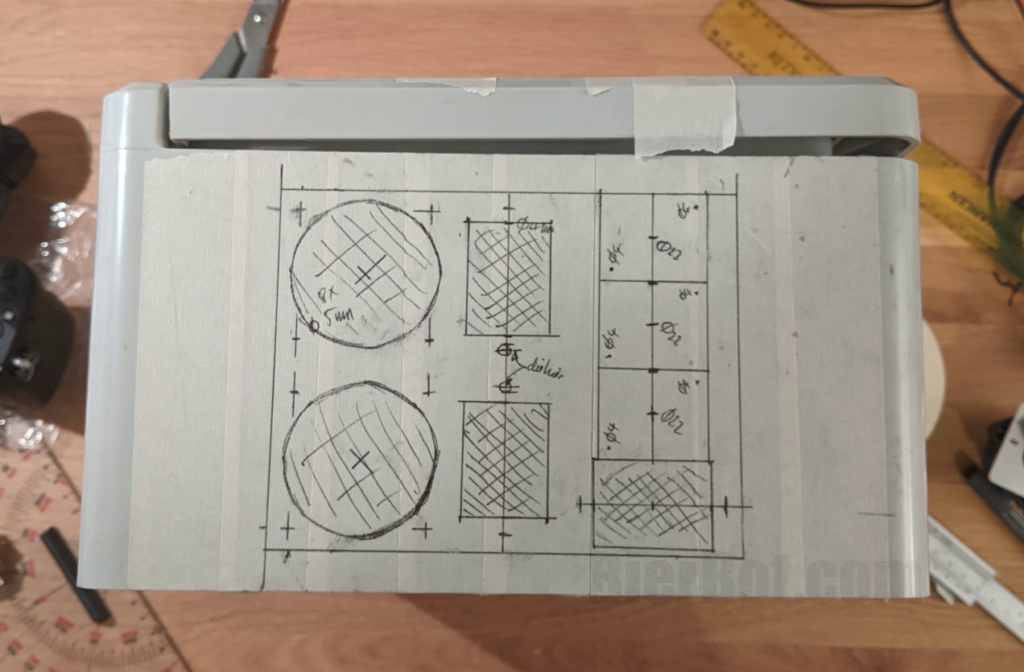
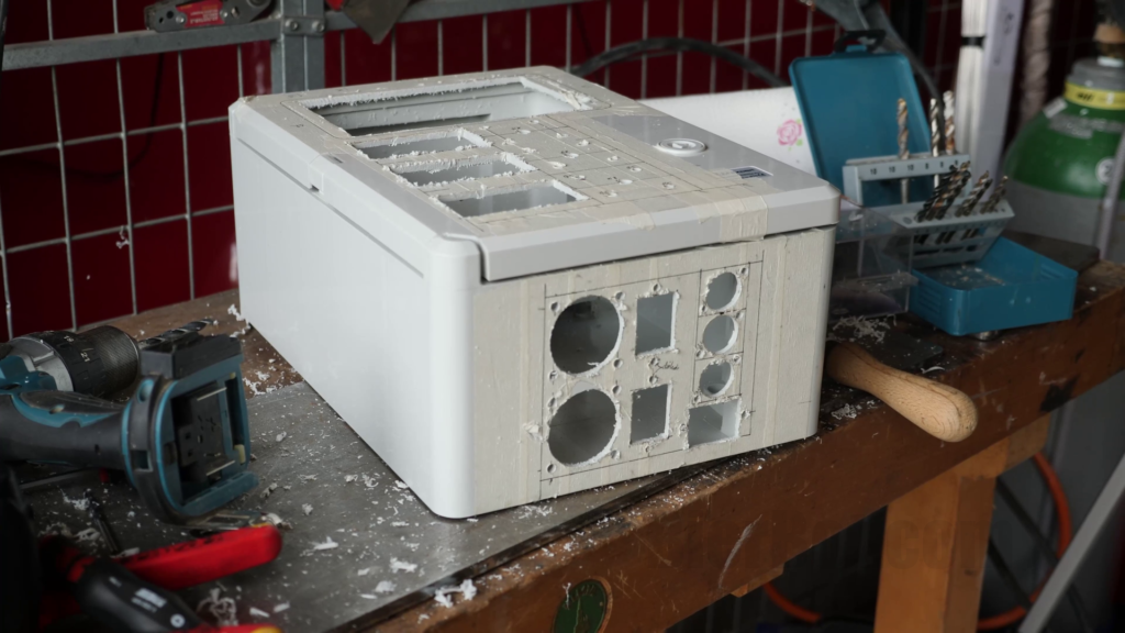
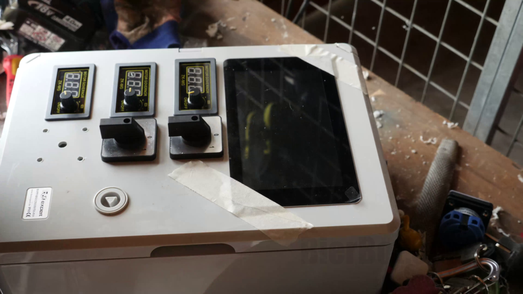
Some words on my layout. The front (from top to bottom):
- RaspberryPi display to show most relevant information about the current mashing or fermentation process.
- 3 DC PWM regulators that can be switched of by the switch next to it. Channel 1 actually supports 3 modes: On, Off, or controlled by the Raspberrry Pi.
- A On/Off switch for peripheral (that was added later 😊)
The bottom includes (from right to left)
- Two, AC sockets for plugging in heating or cooling.
- The corresponding AC-IN is located next to it.
- One AC-IN on the right side to power all DC outs as well as the Raspberry Pi.
- Three XLR sockets to connect DC equipment such as pumps / agitators.
On the left two 2.5mm TSSR jacks were mounted as there was no space left on the bottom 😂.
Important note: The cutout for the RaspberryPi Display is not symmetrical (asymetrical).
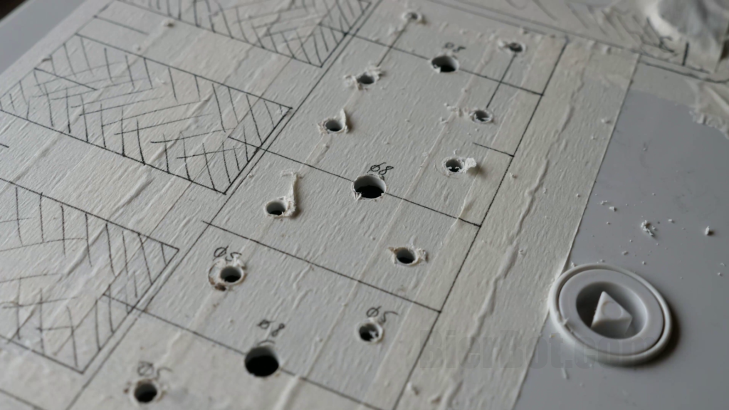
Cutting the housing
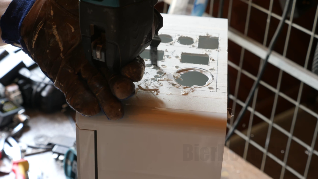
After we sketched where we want to cut it’s now time to the actual cutting / drilling. This is certainly the most time consuming part of the build. Start with the easy holes to get a feeling for the material of your housing. In my case that were the holes for the switches.
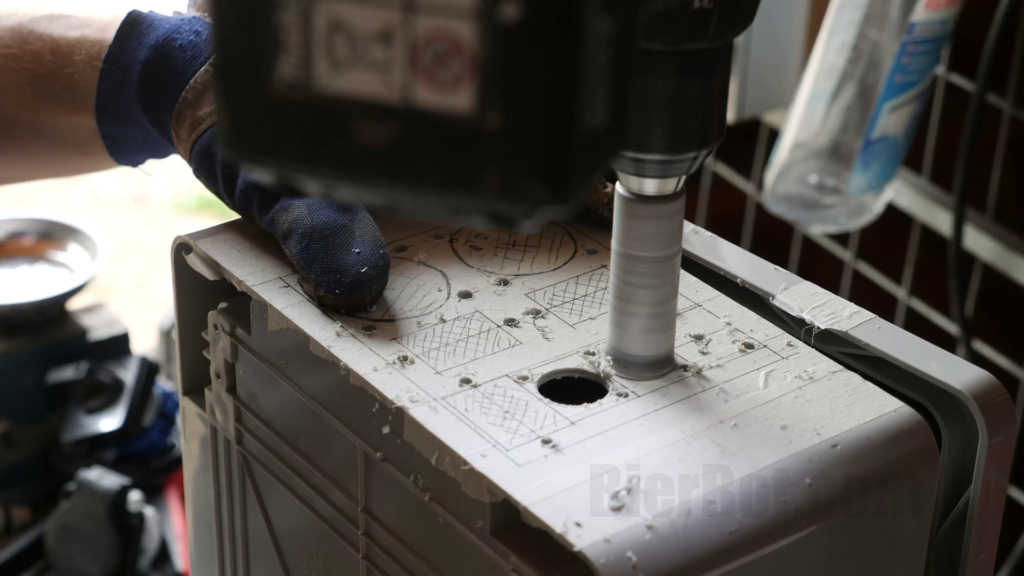
Next step for me was to cutout the medium sized holes for the XLR sockets. I used a “drillsaw” (one that was rated for metal). For cutting / drilling plastic, a wood grade drillsaw is absolutely sufficient. And these come ususally in packages with multiple diameters. Alternative would be to drill the largest hole where you have a drillbit available and then file the rest.
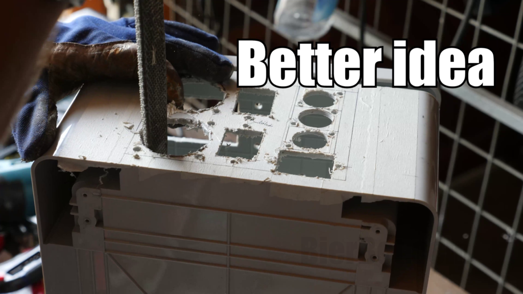
Next up for me was cutting the straight edges, required e.g. for the DC motor governors cutouts and the Raspberry Pi Display cutout. The Multitool from Makita worked like a charm. A Jigsaw will probably also work. As well as drilling and filing – however that will be time intense. A little bit of extra effort was required at the place where the lock is located. My housing had two locks. I sacrificed the upper one for the display in favor of a compact layout.
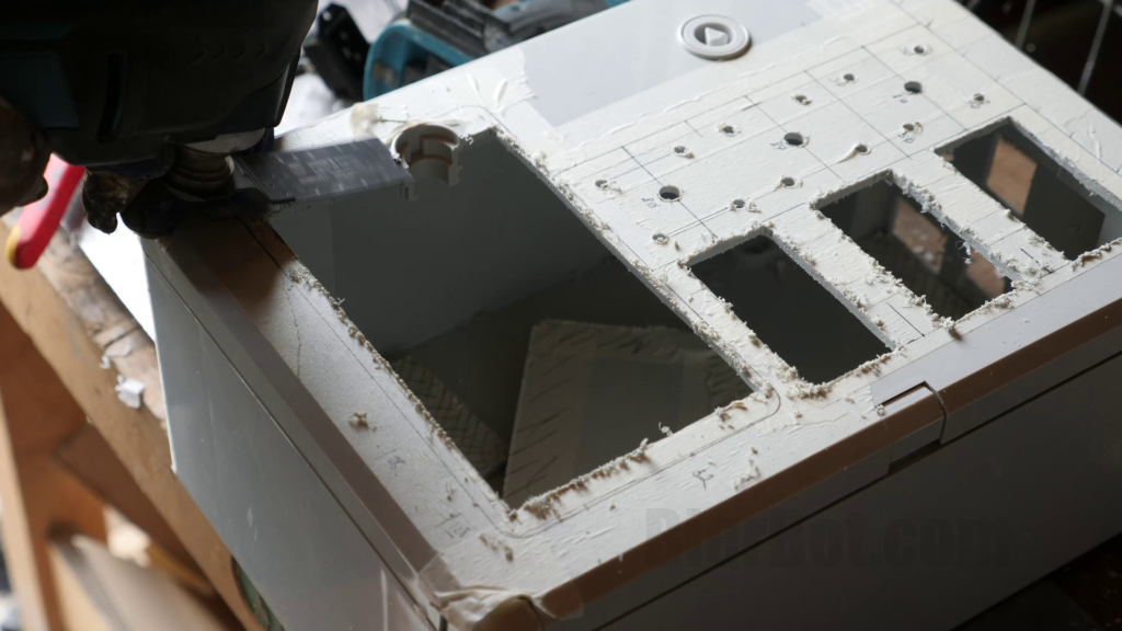
Fabricating the big cut-outs for the AC sockets with approx 40mm / 1.6″ in diameter, this was no easy feat! I’ve tried various tools. What worked best was drilling holes close to the edge, and then using a coarse file (rasp) to do the rest. Ideally, it’s a curved one.
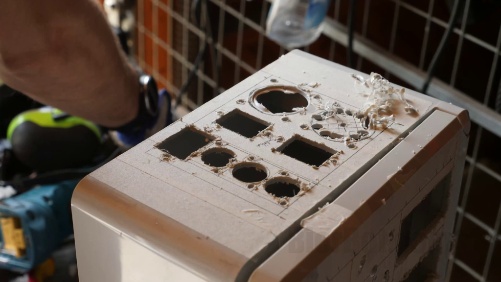

Other than that, how you proceed will depend on the tools you have available. I’ve used several drill bits for small holes, a multitool for straight cuts (display, DC controls), a rasp (big holes) and a cutter to smoothen the rough edges.
I cannot stress this enough: The Raspberry Pi display is assymetrical!
Installing the peripherals (Display, knobs, electic INs & OUTs, etc.)
The knobs
This step is pure joy and the reward for the previous, plastic chip heavy work.
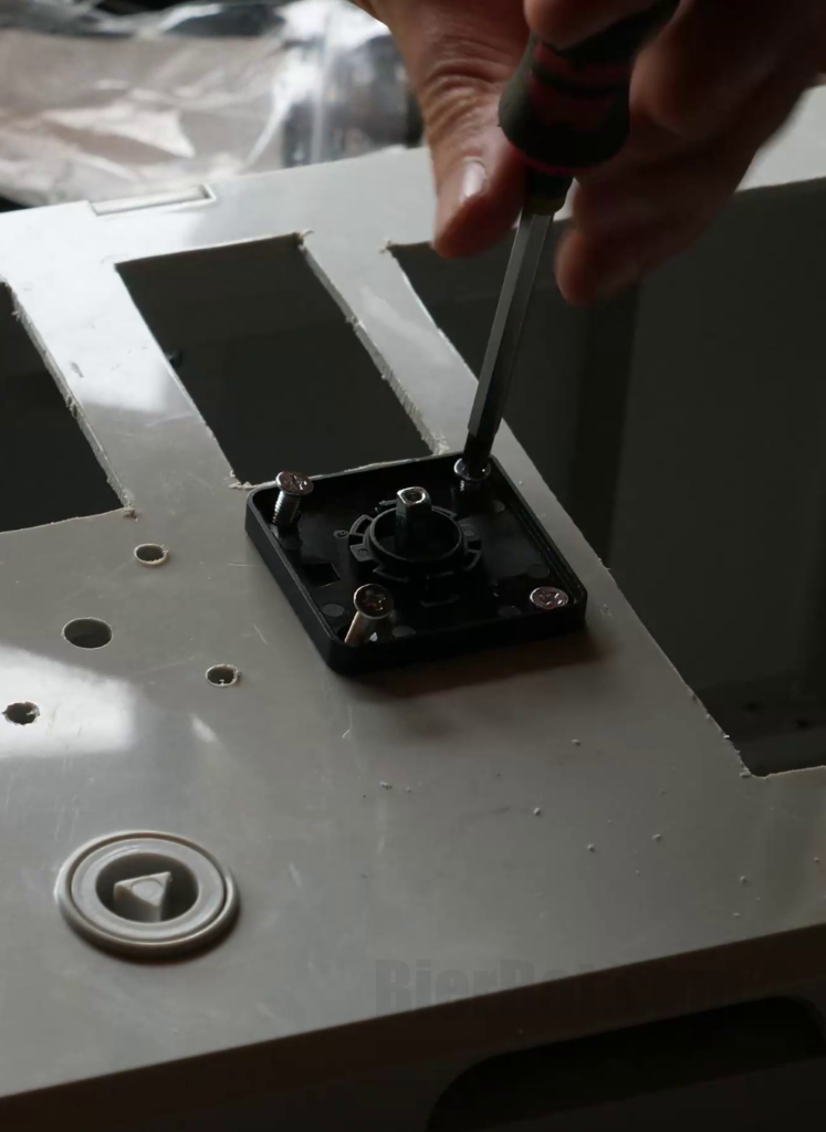
Sandwich the housing between lower and upper part. 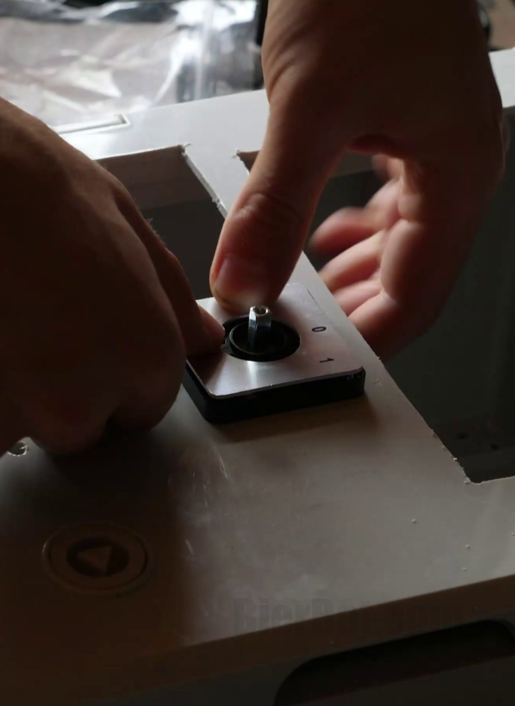
Snap the cover with the labels into place. 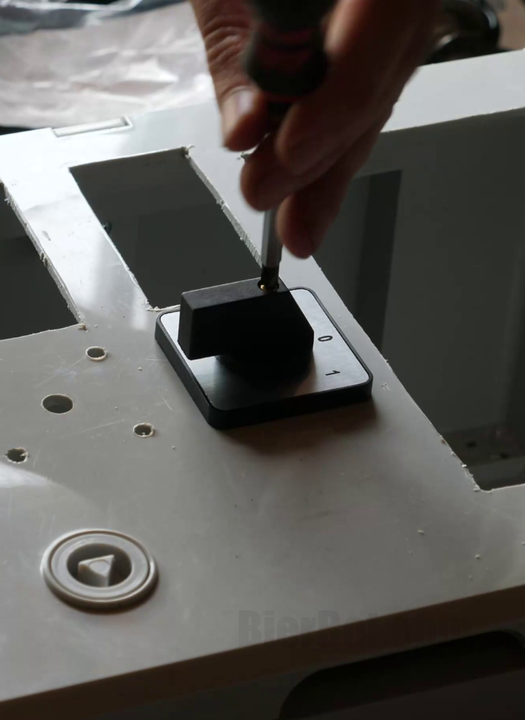
Install the knob.
The knobs are delightfull to install. One of the three knobs I’ve ordered had a dead philips screw. So I had to re-order. I replaced the dead two-way knob (on/off) with a three-way knob (on/off/2) during the build. If position 2 is set, the BierBot software is in control. This allows to automate agitators, pumps, etc. Only thing you can (and I did) screw up, is to mount them in such a way, that the philips screw terminals are not easily reachable. Hint: You can rotate the part that goes into the housing by 90° without changing anything on the outside.
DC motor governors

Cutting the snap ins so that they really snap in 😉 1/2. 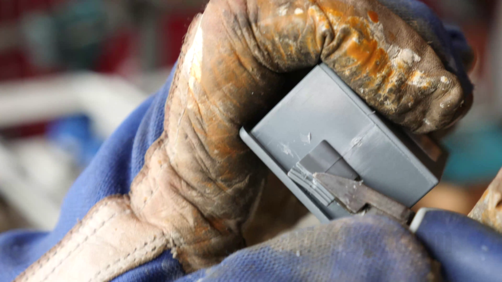
Cutting the snap ins so that they really snap in 😉 2/2.
The motor governors were a bit more finicky. They have a “barb” that’s supposed to snap into place and hold them tight when installed in the housing. Maybe it’s my ape brain, but that did not work out for me. The plastic housing was too thick. So I shortened them and used longitudinal slot screwdriver to force them into place. This worked fine in 5 out of 6 times. One died (R.I.P.), which was replaced by glue.
Raspberry Pi Display
Next thing is the Raspberry Pi Display. I’m not sure why, but they did not include any brackets in the packaging that help you to fix the display into place. So you have to build one yourself. Easiest way for me was to build to brackets out of wood since I had a hand-milling machine around. I’ll save words here and let the pictures speak.

Milling the cutouts for the 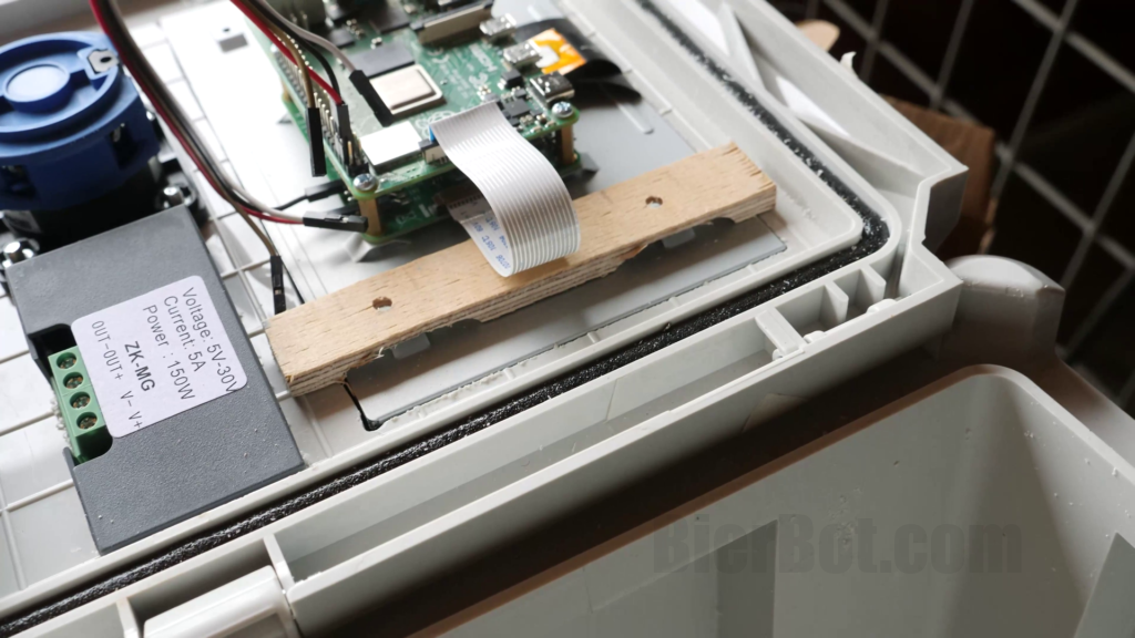
Testing the wooden bracket. 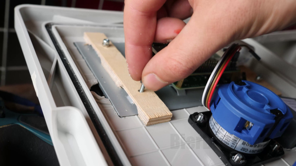
Screwing the wooden bracket in place.
AC and DC inputs and outputs
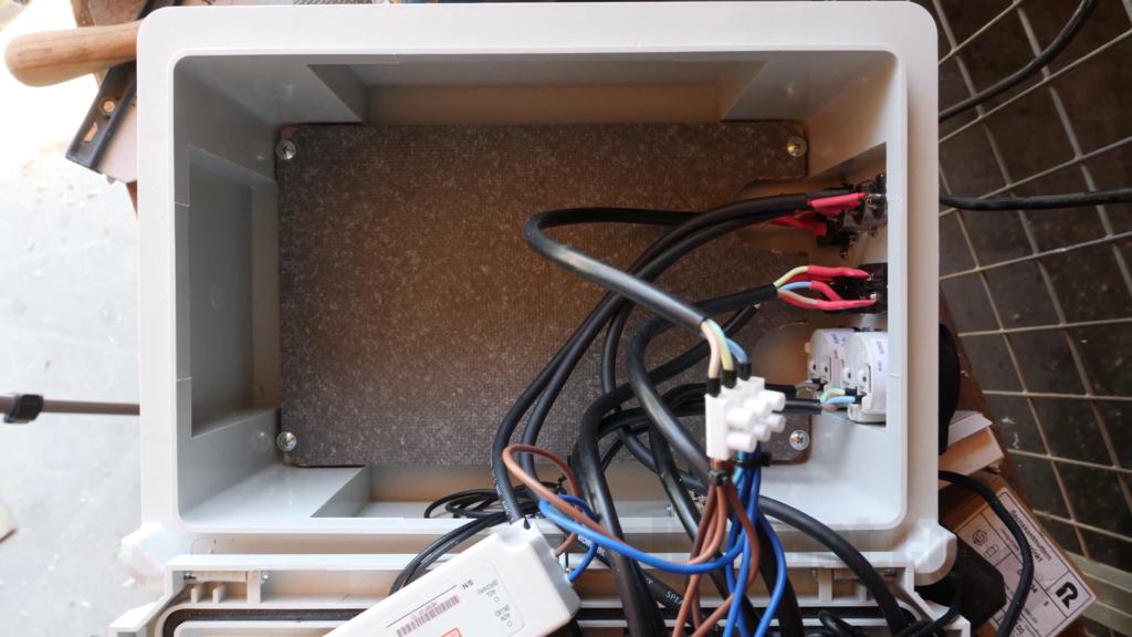
Last thing to do is installing the electrical INs and OUTs (both, for AC and DC) on the lower side of the housing. If possible, I recommend to connect all cables in the respective components (e.g. AC-Sockets, AC-In Terminals, DC-Out terminals) before installing the component in the housing. The terminals are generally better accessible when not yet mounted. In some cases, this is even a necessesity – in my case the screw terminals of the AC-Out-Sockets were blocked after mounting into the housing.
Whereever possible, I’ve used wire end sleeves / ferruls. In some cases the result was to thick to go into where I wanted it to be (this was the case with the relais board or when I tried to stuff 5 cables into one chandelier terminal). The process before preparing a cable is always the same:
- Remove outer cable isolation
- strip inner cable isolation
- Crimp ferruls if connection allows
- Optional: Cut an place shrink hose
- Install cable
- Optional: Move shrink hose into final position and apply heat 🔥
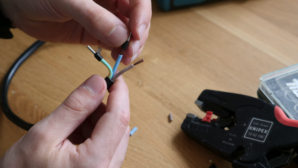
Add ferruls onto stripped cable. 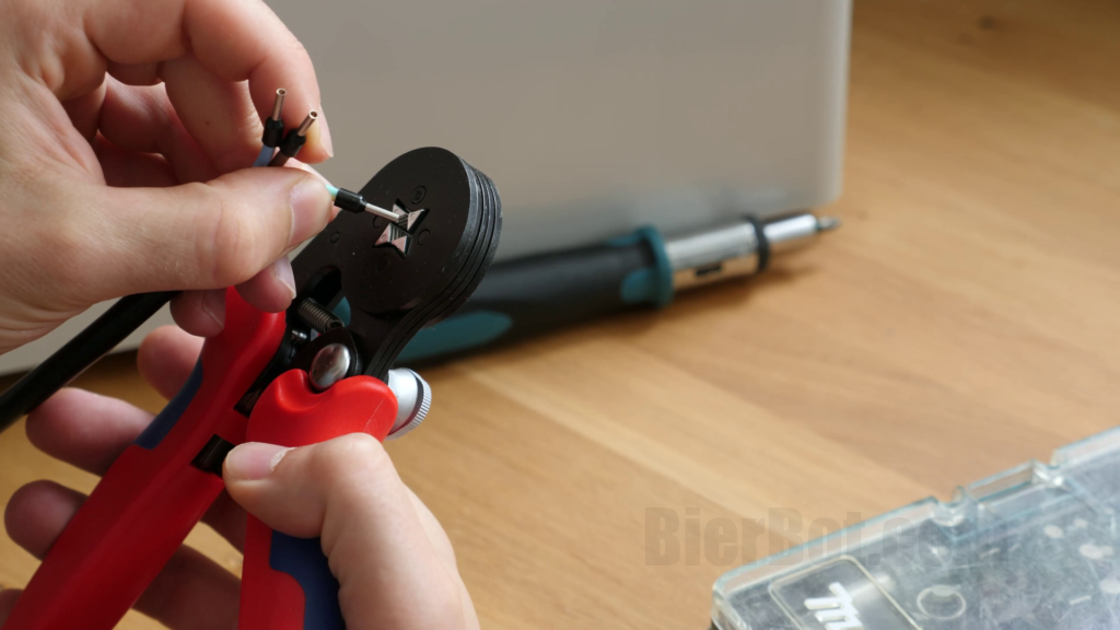
Crimp ferruls (Step 4). 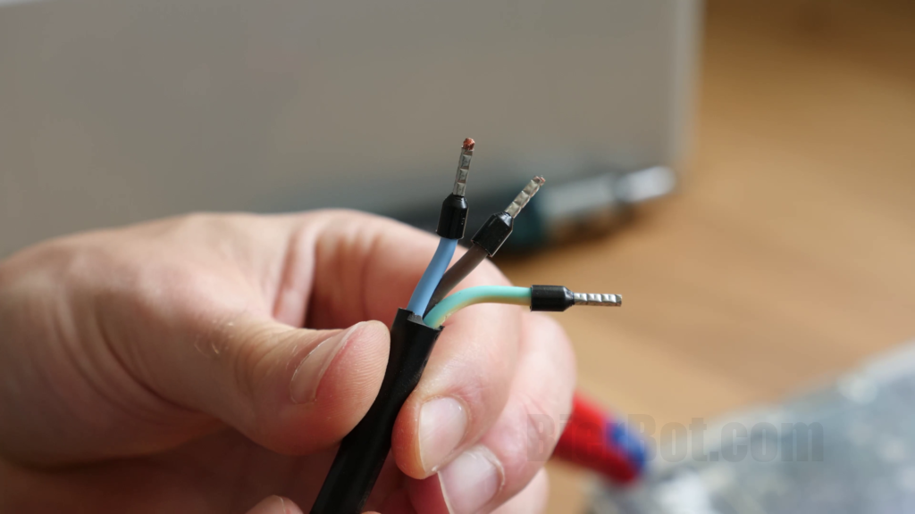
Result.
For the AC Input terminals, usually crimping is required. However, the cables I’ve used were too thick. So I had to solder them (which is not optimal, since the cable might heat up which cause the solder to melt, your brewing control to catch fire, your house to burn down and you to die). Steps 1-3 are the same, step 4 is to solder the cable onto the back of our connector. New step five is to apply heat.
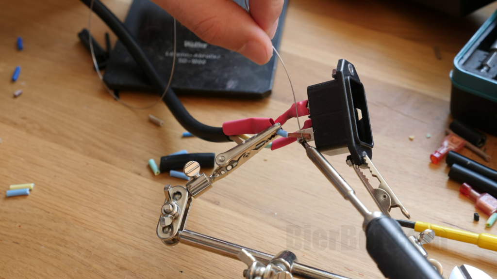
Soldering a cable. 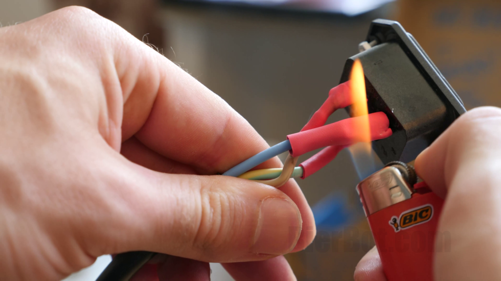
Apply 🔥 to shrink hose.
I gave all cables a little extra length. You can always cut it shorter, the opposite is possible but more labor intense.
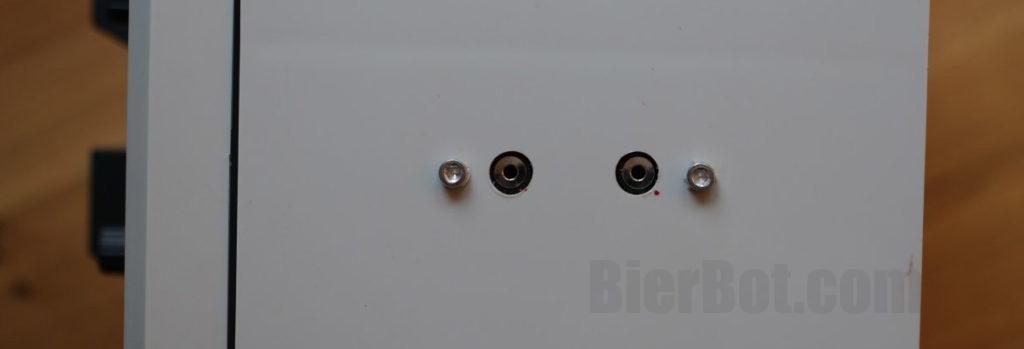
DS18B20 AUX sockets
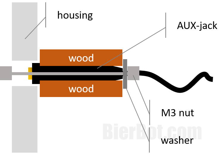
My awesome constrution to expose the AL560 extension cable to the outside is a little bit rogue. BUT it worked (pretty well actually). Baseline is that you mill two parallel tracks into a thin (5mm / 0.2in) piece of wood and cut two stripes of that wood (orthogonally to the milling track). Using a metric screw, I sandwiched the two AUX sockets in the middle. This holds them im place. I think you get the idea by looking at the pictures.
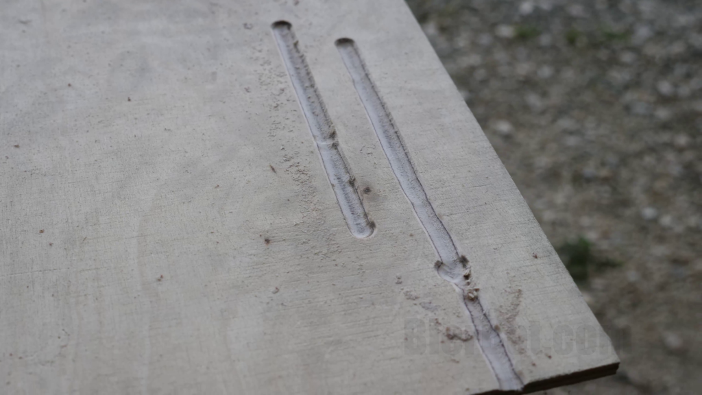
Milling two straight, parallel lines. 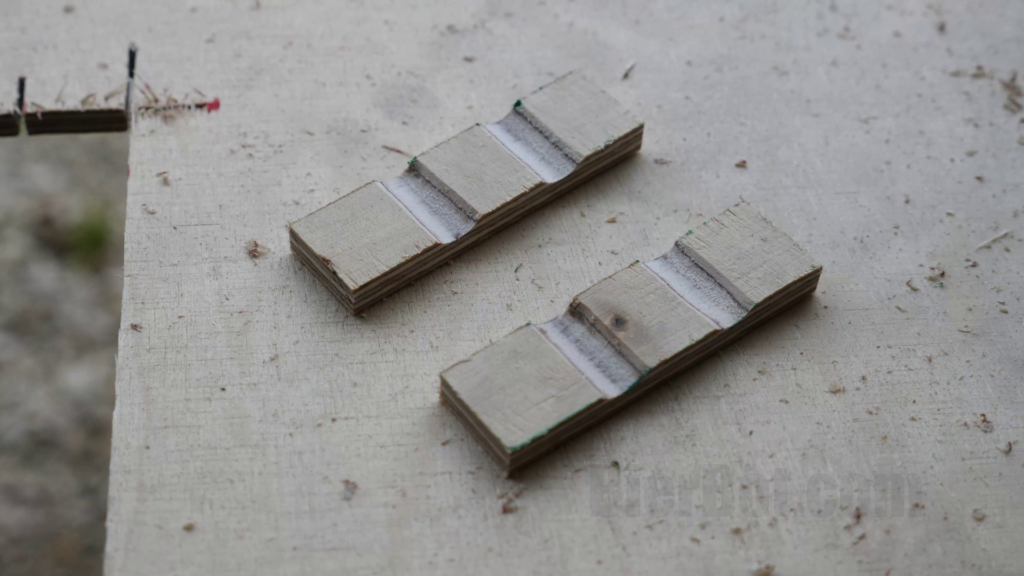
Cutting out two brackets. 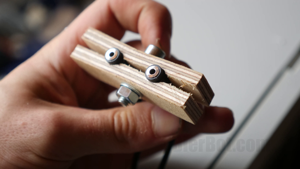
Sandwich the AUX sockets in the middle of the brackets using a metric screw.
To mount the sandwich in the housing, we need to drill four more holes: Two for the AUX-sockets, two for metric screws holding the sandwich in place. Hole drilling was more freestyle in this case: I simply measured the distance of the two sockets in my sandwich and marked that on the housing. I drilled two 8mm / 0.31in holes. Then, I drilled two additonal holes on the outside.
I’ve created a schematic using and hope this makes things more clear (if not, leave a comment below, and I’ll create a proper CAD drawing):
Connecting the dots / wires
Wiring diagram for the rest
The remainder of all connections we will be making is to turn on or off power (AC and DC). Let’s look at a wiring diagram with two simplifications: No Raspberry Pi display, I actually have two AC-DC-converters powering my DC out 1 (and only one is displayed). We will skip how to setup the Raspberry Pi display, since there are countless tutorials on the web how to do so.
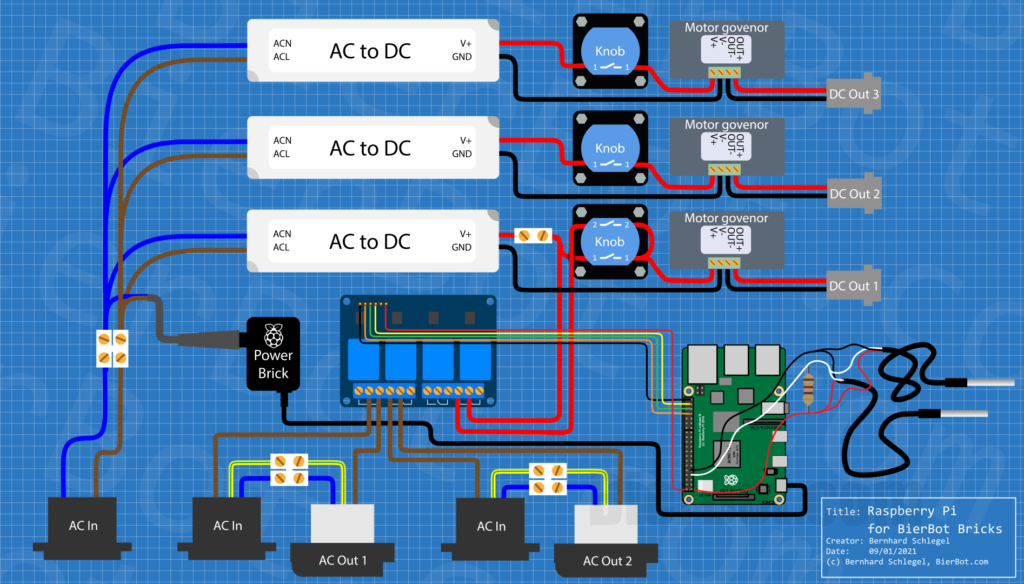
Let’s start from lower left to right. You notice three “AC In”s. One is powering all DC Outs (1-3) and the Raspberry Pi. That’s the one on the very left. The other AC Ins (2 & 3) are powering only the corresponding AC Outs.
AC In 1 on the left, is routed to the AC inputs of the AC to DC converters, as well as the ending of a AC extension cord that I’ve cut. The other end of the extension cord (the socket) is used to plug in the Raspberry Pi Power Brick. That’s the black cable, going from the lower side of the Power Brick to the USB port of the Raspberry Pi.
The upper two DC circuits (including the AC to DC converters) are exactly the same: GND (black) is routed straight to the motor govenor. Red (24V / plus) is routed through a knob which can be used to switch on/off the DC out manually. The motor govenor steps down the supplied voltage (24V) in 100 steps. The output of the motor govenor is routed to the DC Out 1 – which I implemented as XLR socket.
The lower DC circuit is different. While the previous knobs only had two positions (on/off), this one has three: Always On, Always Off, and (that’s the clue) controlled by the BierBot Brick software. Position 1 is the same as with the two DC circuits above: It just forwards the supplied 24V to the motor govenor (always on). If Position 2, the 24V are not coming from the AC to DC converter directly. Instead, the 24V from the converter are routed through the 4 channel relay board located at the center of the drawing. This can be controlled (turned on / off) by the BierBot Bricks software. If, and only If the relay is “on” the 24V coming from knob position 2 can proceed to the output of knob position 1, which leads to the motor govenor.
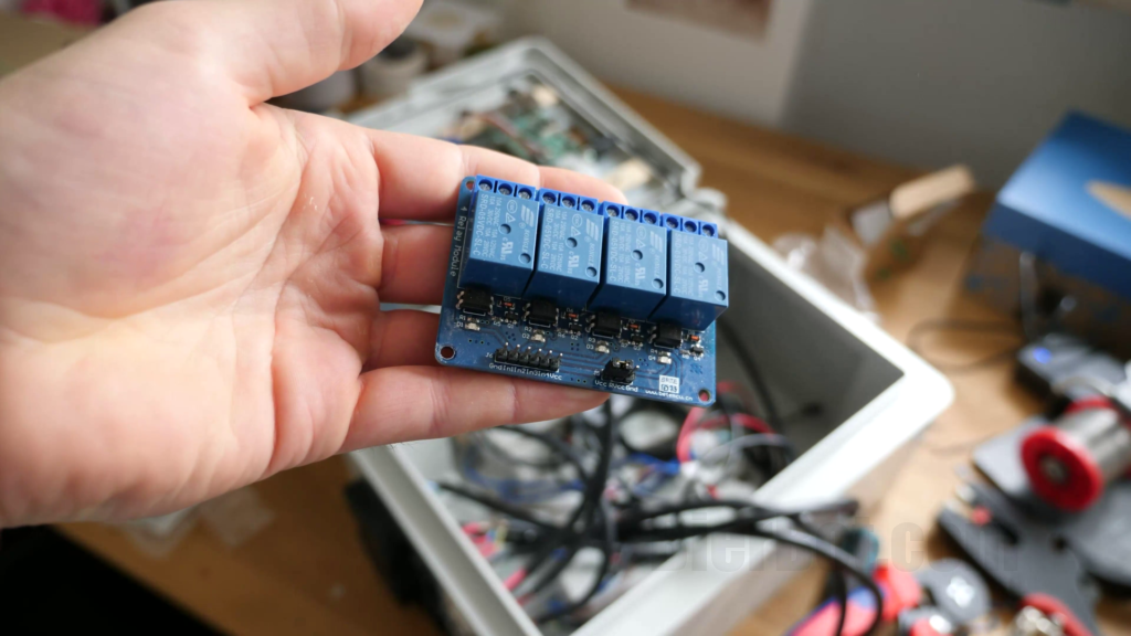
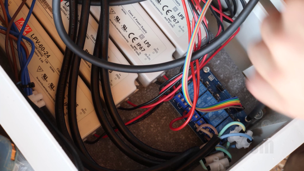
The 4 channel relay board up to 10A per channel. 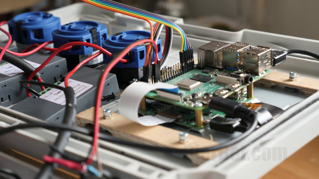
Connnections to the Raspberry Pi. 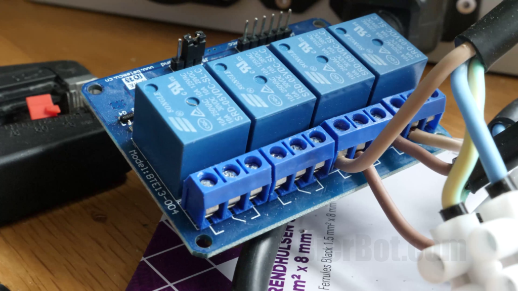
Brown AC (L) wire going into channel 2.
Speaking of the relay board in the middle. We only use three of the four channels it offers. We’ve already discussed one (the DC Out 1). The other two are used for controlling the AC outs. To achieve that, the brown (L) cable is routed through the relay. The blue (N) and yellow-green (mass) cable are always connected and go from the AC in straight to the AC out. The relay board is supplied with 5V (red cable that goes to the most bottom left pin of the Raspberry Pis pinheader) and GND (black cable, top-right pin of the Raspberry). The other three cables (yellow, green, orange) are connected to the pins below the GND pin on the Raspberry Pi. These will carry the signal to turn on / off the relais.
Now, that we arrived at the Raspberry Pi there is one thing left to discuss: The temperature probes. The sensors we are using are DS18B20 temperature sensors that are connected using 1-wire (1W) protocol. We just need one wire for data – thus the name. That’s the white one. Unlike the pins controlling the relays, this (white) wire, has to go to GPIO4 / Pin 7 since this is the only one that speaks “1-wire”. Connect the red (V+) and black (GND) cable as shown – they supply the power. The cool thing about the 1W protocol is, that you can connect multiple DS18B20 sensors to these three (white, red, black) cables. And that’s exactly what I did – I’ve used two sensors. One more thing: For the sensors to work, we need a “pullup resistor” that bridges from the white (data) to the red (V+) cable. Ideally, this should have 4.7kOhm. I’ve used 5kOhm.
Don’t do cable management yet and don’t forget to vacuum at the end to get rid of all the plastic chips. In reality, that looks like this (don’t be confused, that’s how it looks when you’re completely done):
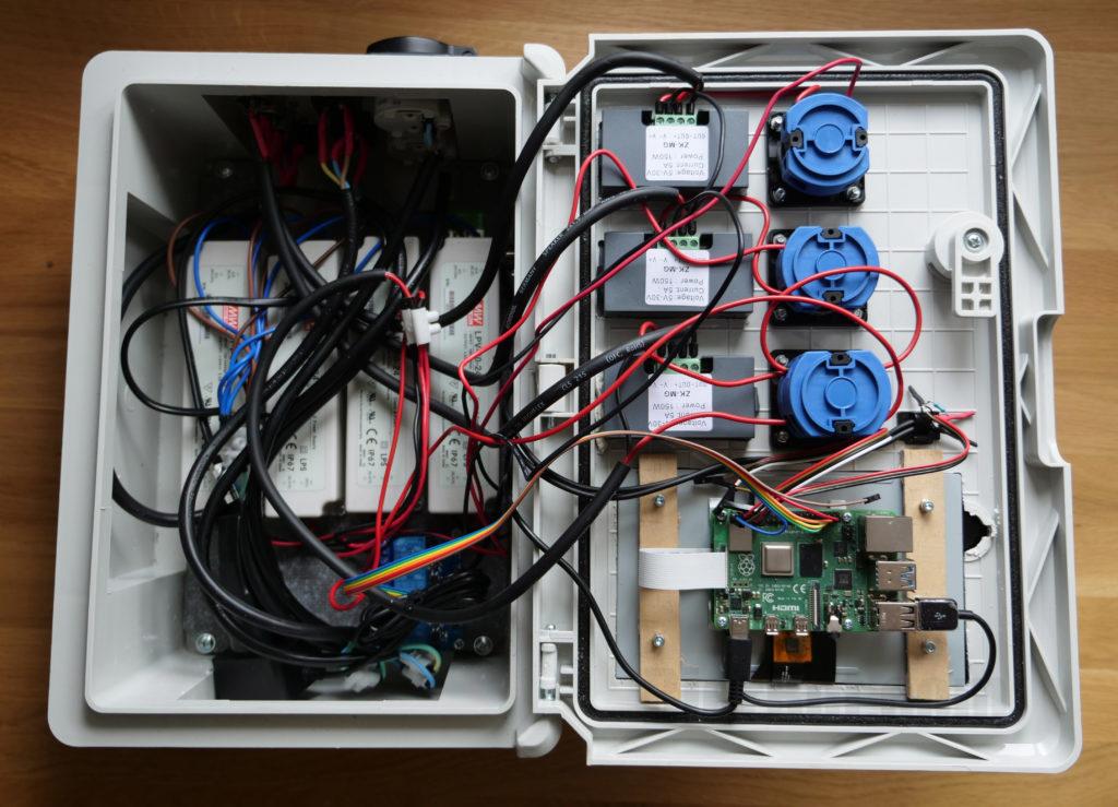
As the Raspberry Pi is mounted in the lid and the relais board is mounted in the lower part of the housing, connecting those two requires a longer-than-usual rainbow cable. While “usual” refers to 20cm / 7.8in I used a 40cm / 15.6in long in this case.
DS18B20 temperature Sensors using AL560 extension cable
As you know from above, I used AL560 extensions cables to have a nice AUX socket where I can plug my temperature probes into. I know – this is not what’s displayed on the blueprint above, sorry! The joint of the AL560 with jumper cable going to the Raspberry Pi was the place where I’ve installed a 4.7kOhm pull-resistor between Data and 3.3V. Pullup resistor is just fancy for a off the shelf resistor, that pulls a GPIO “up” towards 3.3V.
If you’re using the AL560 cable as I am, mapping is “interesting” (seriously, who fucked that up?) to say the least:
| Color AL560 | Meaning | Jumper cable color (on my images) | Raspberry Pi |
|---|---|---|---|
| Black | 3.3V | Brown | 3V3 (Pin 1) |
| Red | Data | Red | GPIO4 (Pin 7) |
| White | GND | Black | GND (Pin 9) |
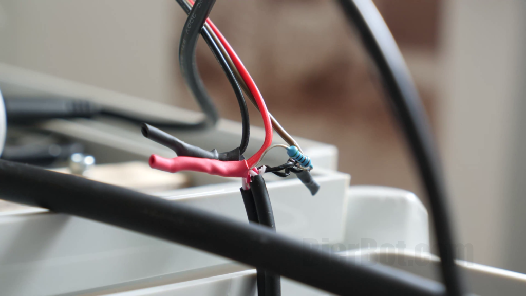
Joint of AL560 and Jumper cables going to the RPi. 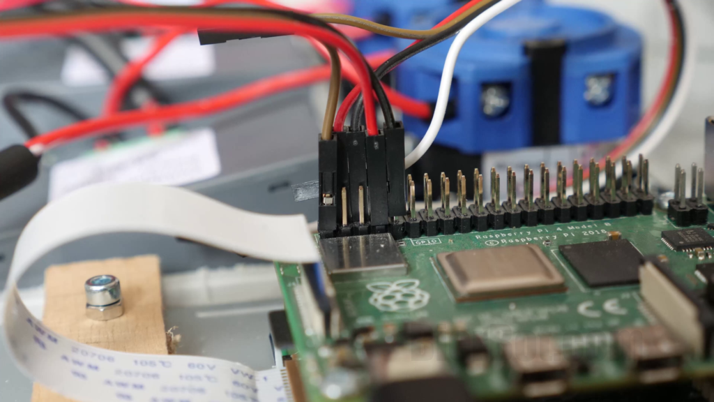
Connection on the Pinheader of the Rpi
By the way: Since the 3.3V is located next to the GND on the TSSR AUX jack, you will cause a short circuit upon inserting (unless your inserting it perfectly centered and co-axial). Thus: Plugin your temperature sensors before powering up. If you have a simple idea how to solve that, drop a comment!
Building a baseplate and mounting everything on it
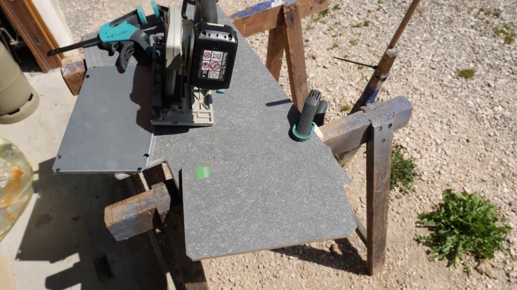
The housing came with a metal baseplate. However, I decided to build my own wooden one for two reasons: First: mounting components is much easier when you can just use a self-cutting screw from the top. Compare that to having to mark and drill every hole in advance and hold nuts in place while screwing. Second: I had to create two cutouts to avoid collisions with the AC-in and OUT-Outputs. Doing so is easier with a jigsaw than with a angle grinder.
Aside from the 2 cutouts to avoid collisions, I drilled 4 holes in my new baseplate. These holes are a replica of the holes the original, metal one has. The holes are necessary for the screws that bolt the baseplate into the housing. I was lucky, that the screws were long enough to still work with my much thicker wooden baseplate. Check that in advance if you decide to go the wooden way!
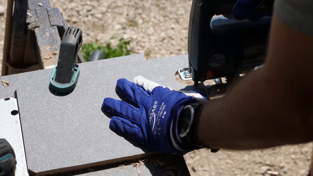
Cutting out parts of the baseplate to … 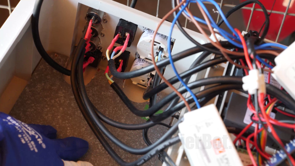
… avoid collisions with the AC in and outputs.
As Planned, screwing everything into place, was a very satisfying almost dream-like experience. I’ve used Spax 3.5 x 12 Z2 screws (which is just meant to serve as inspiration).
Since the lower side of the relais board is not flat (some DIP parts…), I’ve used spacers between the PCB of the relais board and the baseplate.
Testing the essentials
I advise to test – whenever safe – intermediate results. The Github repo (folder “test”) has two Python files, one for switching relais and one for reading temperature values.
Installing and configuring the software
Now it’s time to setup the Raspberry Pis operating system “Raspbian” and the BierBot Bricks homebrewing software. There are plenty of tutorials on the web how to do the first, so I will only cover this briefly. The focus is on the latter.
Setting up the Raspberry Pi
First, insert die microSD card – presumambly using an adapter – into your PC or Mac. Second, head over to raspberrrypi.org/software and download the “Raspberry Pi Imager” tool. After download, open it.
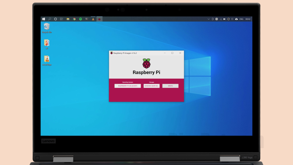
It will ask you for admin permission to get full write acces to your SD card – which is OK. Select the “Raspbian” as OS, your SD-Card as target. Hit “flash”. After flashing and verification is done, insert the SD card into your Raspberry Pi.
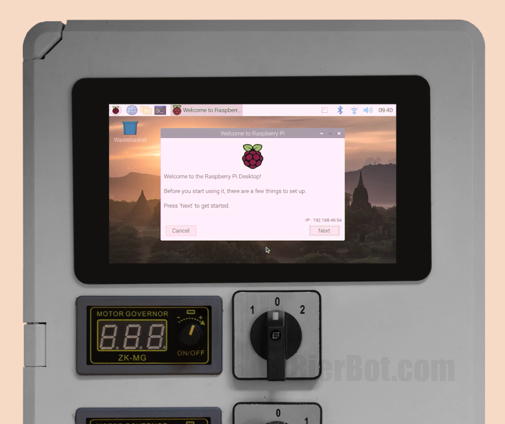
It will automatically resize the filesystem and reboot – don’t worry. Shortly after you’ll be presented with the Desktop! Use the wizard window to setup your Raspberry. It will ask you for selecting the language, keyboard layout, region and WiFi settings and update the software for you. Do not reboot just yet.
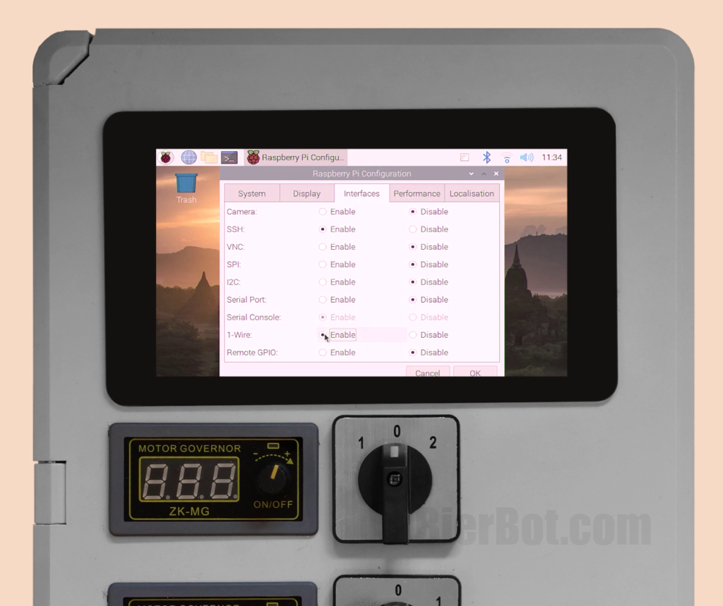
Head over to Menu > Preferences > “Raspberry Pi Configuration” and selected the tab “interfaces”. Set 1-Wire to “Enable” – we need this for the temperature sensor to work. After this is done, hit reboot!
Setting up the BierBot Bricks homebrewing software
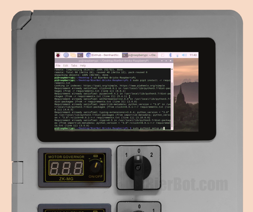
Now it’s finally time to install the actual brewing software! We will use the code from that’s available for free on Github. Follow the steps described in the “Getting Started” section. Paste the following lines into a terminal (to open one, hit Ctrl+Shift+T):
cd ~/Desktop
git clone https://github.com/BernhardSchlegel/BierBot-Bricks-RaspberryPi.git
cd BierBot-Bricks-RaspberryPi
sudo pip3 install -r requirements.txt
python3 setup.py
The setup script will start and guide you through the setup process. Answer the questions about your setup and hit Enter to confirm.
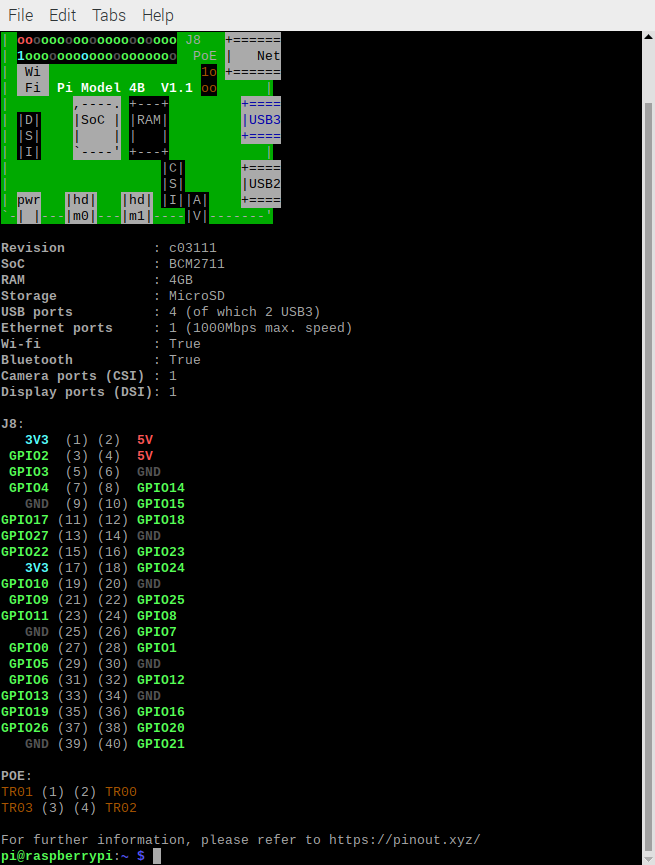
Opening a second terminal and executing “pinout” might be handy if you are not sure about which GPIO numbers you’ve used. So I’ve connected GPIO 26, 19, 13, and 6 to my relais board. GPIO13 is special, since It can do PWM. In your config file (see Section below), you will need the “31”, “33”, “35” and “37”.
Future work
This section might serve as inspiration how to improve this build further:
- PWM for AC out using a solid state relais (SSR). Attention: This will generate a lot of heat. So the housing will require most likely a fan.
- Using a relay board which supports more than 10 ampere as i.e. this.
Questions, Feedback, anything?
Big Thanks if you made it till here! If you found this tutorial helpfull or have questions: Please leave a comment! If you successfully completed a BierBot build, shoot us a message – we’ll send you a BierBot sticker for free! Please be sure to attach a photo so we can share it here.
Common issues / FAQ
Fix wrong screen orientation
If you are forced to install the Raspberry Pi Display rotated, there is a solution. Open the config file using “sudo nano /boot/config.txt” and paste one of the following at the end. If your using a touchscreen (and want thus to rotate screen and touch) use “lcd_rotate=3”. If you just want to rotate the screen use “display_rotate=3” for 180 degrees.
Raspberry Pi 4: No HDMI output
Thanks to this, I was able to get output by adding the following lines to /boot/config.txt (open an editor by typing “sudo nano /boot/config.txt” in the terminal):
#fix for rpi 4 models with dual hdmi
hdmi_force_hotplug:0=1
hdmi_force_hotplug:1=1
hdmi_drive=2
Hallo Bernhard,
Vielen Dank für die Inspiration für den Bau einer eigenen Brausteuerung. Ich habe das Bierbot- Programm auf meinen Raspberry Pi 3+ geladen und beim Öffnen von Bricks.bierbot.com/#/status wurde die Seite nicht erreicht. Habe ich evtl. einen Fehler im Api key gemacht? – vielleicht kannst Du mir helfen. Gruß Carsten
Hi Carsten, sorry für die späte Rückmeldung (hab keine Benachrichtigung über einen ausstehenden Kommentar bekommen). Wenn die Seite Bricks.bierbot.com/#/status nicht läd, liegt das eher an mangelnder Internetverbindung / WiFi. Du kannst du probieren die Seite erst später zu Öffnen. In python wäre das für 30s warten:
import time
time.sleep(30)
Einfach in der main.py einfügen bevor die Seite geöffnet wird.
Viele Grüße,
Bernhard.
Hello Bernhard Schlegel, I am new at Brewing System and I have a question what are the motor governors and dc out used for?
Hey Austin, sorry for the late reply. The DC outs are for controlling my DC pumps and whiper motor for stirring (which is also DC). Cheers, Bernhard.
Hi Bhernard
Congratulations on your job well done and sometimes funny.
I state that I’m not a computer engineer and I’m not very familiar with communication protocols.
So, until the installation of the Raspberry Pi software on the and initial reboot everything is ok. Perfect!!!
After the reboot I see that you move remotely (it’s can see your mouse), and here’s my simple question for you: but how did you connect your pc to the Raspberry Pi??
At the bottom right on your video, after reboot, it’s can see an IP address, did you enter it? How?
Have you paired Raspberry via home router? How?
Or did you just pair computer and Raspebrry via Bluetooth? How?
How did you take control remotely via PC?
Sorry for my lack of computer knowledge, but I need this step to continue with the implementation of your nice project.
Thanks, and many congrats again
Mauro
Hey Mauro,
Thanks for the kind words. To remote control your Raspberry Pi you can open a terminal (on windows i.e. by hitting Win+R, typing “cmd”, hitting enter). Simply type “ssh 192.168.2.42” and follow the prompt to provide username and password. 192.168.2.42 has to be replaced with the IP of your Raspberry Pi. You get it by browsing to your router UI with your browser and checking for connected devices.
Cheers,
Bernhard.
Tks Bernhard
always precious yours suggestions
This how-to is awesome and gives me some good ideas for another home-brewery project! Thanks for publishing! Question, I’m looking at this Pi/touchscreen bundle.
https://www.rasppishop.de/pi4-8gb-all-in-one-bundle
Do you know if I remove the housing on this model, will the touch screen install like the one you recommend in your blog? Rasppishop doesn’t show any pictures of the back of touch screen display.
Cheers,
Daryle
Hi Daryle,
as far as I see the website lists “this article consists of”. I used the same display (check the parts list). I recommend to get just the parts you really need 🙂
Cheers,
Bernhard.
Hi Bernhard,
first of all congratulation for your amazing job.
I’ve seen a lot of times your tutorial and read that post. However, there’s something that I can’t understand.
For instance, why did you plug together two temperature sensors with a 4.7 khom resistor? How can you control them separately from the software?
Can you please explane me wich harware are you managing with your configuration?
I really tried to find an answer on my own before asking tou, but I can’t manage to go through it.
I’ hope you’ll find a little time to spend answering me. Otherwise thank you anyway and cheers (or prost)!
Hi Riccardo,
thanks for the kind words. To answer your questions:
1. Two sensors sharing the same wires work, as the sensor used is a DS18B20 1-Wire sensor. 1-Wire enables digital signal transmission. Every sensor has an ID that it’s sends along with it’s temperature reading. So the softwar can distinguish between them – even if they use the same signal. The resistor is for “making the signal easier to read”.
2. You can checkout our brewing setup here: https://www.instagram.com/p/CohqQ3lNHDQ/ – we’re using two relays and two temperature sensors.
Cheers,
Bernhard.
Dear Bernhard, I’ve recently bought a induction cooktop with 3500 watts of electric power. How did you configurate yours so it will be compatible with the brewing system?
kind regards,
Sam Wuijster
Hi Sam, glad you found us. You need a cooktop that goes “full on” when being plugged in (powered up). What do I mean by “full on”? Not just standby on but also heating like before it was turned of. We, i.e. use the Heidi 3500W which has a physical knob. Cheers, Bernhard.
Hi Bernhard , I’m interested in starting brewing beer and I’m also skilled with computers and electronics and love your project unfortunately I’m have no idea on what equipment I need so it will connect and work with this project, can you specify the brewing equipment you are using ? Pump , cooling/heating for fermentation temperature control ,
I’m looking for buying equipment for all grain brewing.
Thanks
Gild
Hey Gild, glad you found us! Actually, I wrote an article just about that: https://bierbot.com/blog/howto/brewing-hardware-overview-for-beginners/ If you’re missing something, please let me know. I’m happy to publish a “What we’re brewing with” article. In general, this project is very versatile. You can control just about anything that can be switched on/off by a relay (pump, heating, fridge). Only important thing is, it starts cooling / heating / pumping as soon as it’s powered up.
Cheers,
Bernhard.
hi,
can i install 64 bit or 32 bit is required?
thx
gilad
Hi Gilad, it will work with both. Cheers, Bernhard.
Hallo Bernhard,
erstmal Glückwunsch zu diesem tollen Projekt, leider brauche ich bei der Installation auf dem Pi etwas Hilfe.
Ich habe einen Pi4 mit 32bit OS. Beim Ausführen von “sudo pip3 install -r requirements.txt
python3 setup.py” erhalt ich die Fehlermeldung:
error: externally-managed-environment / to install Python packages system wide, try apt install python3
Was mache ich falsch?
Hi, Bookworm braucht ein leicht geändertes Setup. Dieses ist bereits hier https://github.com/BernhardSchlegel/BierBot-Bricks-RaspberryPi/pull/19 beschrieben. Bisher konnte ich das noch nicht testen, daher ist das noch nicht auf dem master. Wenn es bei dir geklappt hat, schreib mir gerne eine Nachricht per Mail, dann gebe ich das für alle frei.
Gut Sud,
Bernhard.
Hallo zusammen, habe mir nun auch ein Pi5 geholt und die Dateien wie in der Anleitung abgeändert. An dem Installationsfehler hat es zwar nichts geändert, aber nachdem ich die Module einzeln über PiP installiert hatte mit “pip3 install *** –break-system-package” ging es dann doch.
Danach konnte ich die Setup.py reibungslos aufrufen. Jedoch wird mein Pi5 nicht in meinen Bricks angezeigt, obwohl ich meinen API-Schlüssel korrekt kopiert hatte. Ab wann wird denn der PI5 als Brick angezeigt in der Weboberfläche?
Gruß Rüdiger
Hallo,
Entschuldigung für das späte Feedback. Ich hatte leider keine Zeit mein Projekt voran zu treiben.
Die Installation hat funktioniert, jedoch waren in der Setup.ph in Zeile 93 ein falscher Pfad und im Sys Ordner fehlte das neue Template. Nachdem das korrigiert war, lief die Installation.
Nun habe ich das Problem, dass ich maximal 5 Aktoren am Pi angezeigt bekomme, obwohl ich die Pro Version habe. Ich benötige min. 3 Temperatursensoren und 6 Relais. Ist das möglich?
Vielen Dank
Hi Bernhard, do you think this relay could work with Bierbots raspberry pi?
https://electronicaymas.com/reles/modulo-2-reles-5v-30a-high-low-level-9994
I had problems of burning in 10A heating relay. Are they the same connection cables? What about COM connection? Is it necessary or not? Many thanks for your help.
Regards
Hey! Yes, These will work